
ANNO Facade Lighting Engineering provides full-process services for global engineering electrical construction drawings, including eight professional drawing systems: material and equipment list, electrical system diagram, control schematic diagram, plan electrical diagram, plan control diagram, elevation electrical diagram, elevation control diagram, and lighting installation drawing. Through standardized design and meticulous construction guidance, we ensure that the project meets international standards and achieves efficient and accurate implementation. We provide safe and intelligent electrical solutions for projects with professional drawings and rich experience.
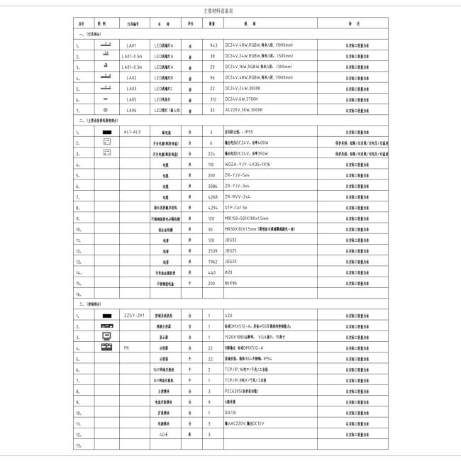
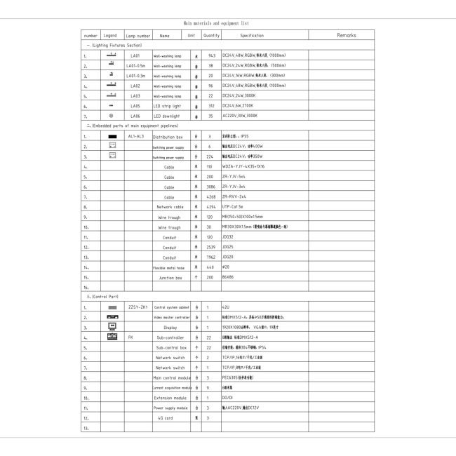
Provide a list of engineering materials that meets IEC standards. The materials include international certification information, technical specifications, etc., to ensure accurate docking from design to procurement, effectively control project costs and progress, and avoid material waste.
Use CAD professional software to draw standard electrical system diagrams, clearly showing the distribution level, circuit allocation and protection coordination relationship. The drawings mark key parameters such as voltage drop calculation and short-circuit capacity to ensure safe matching of distribution systems at all levels, and provide authoritative electrical architecture guidance for project implementation.
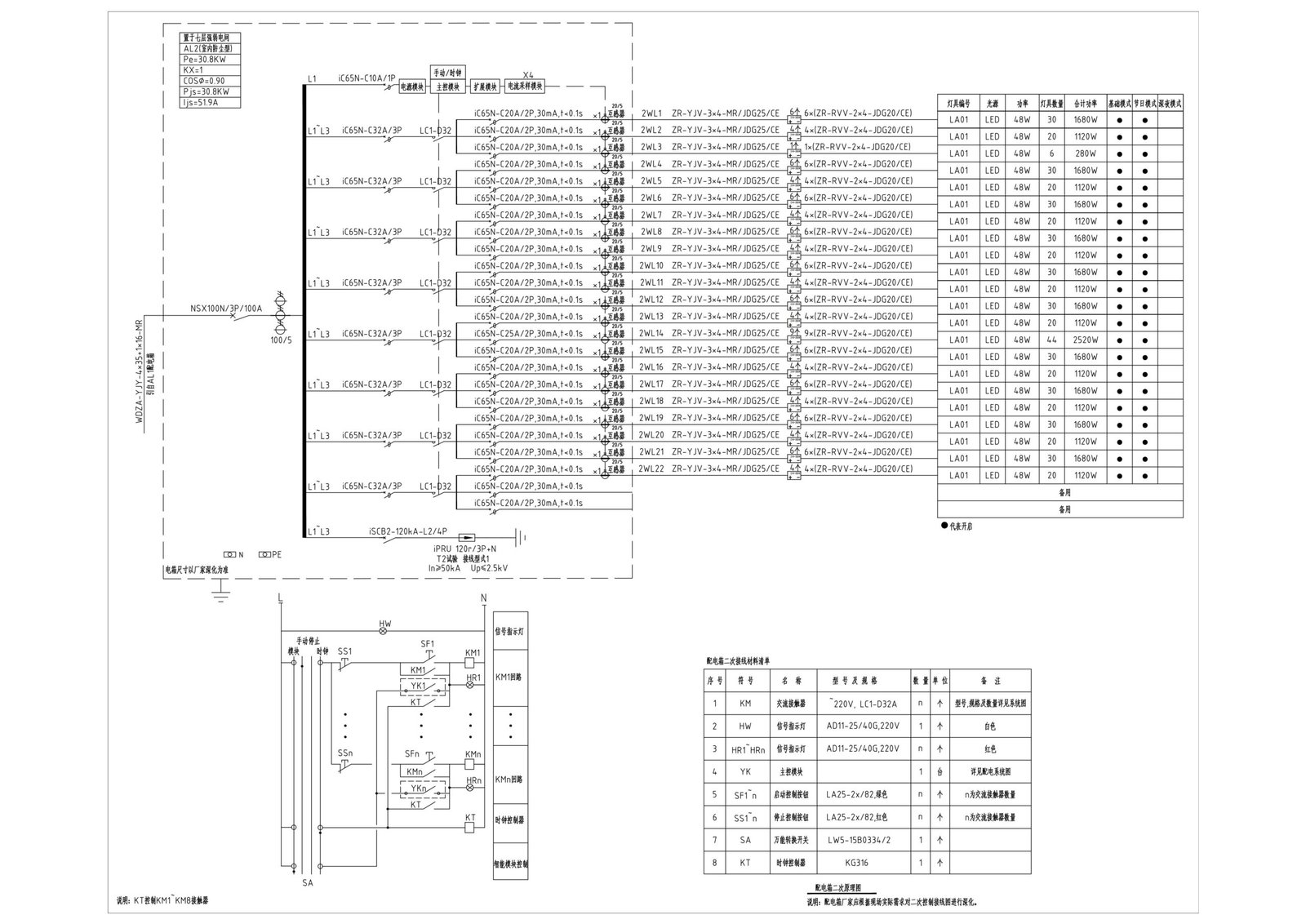
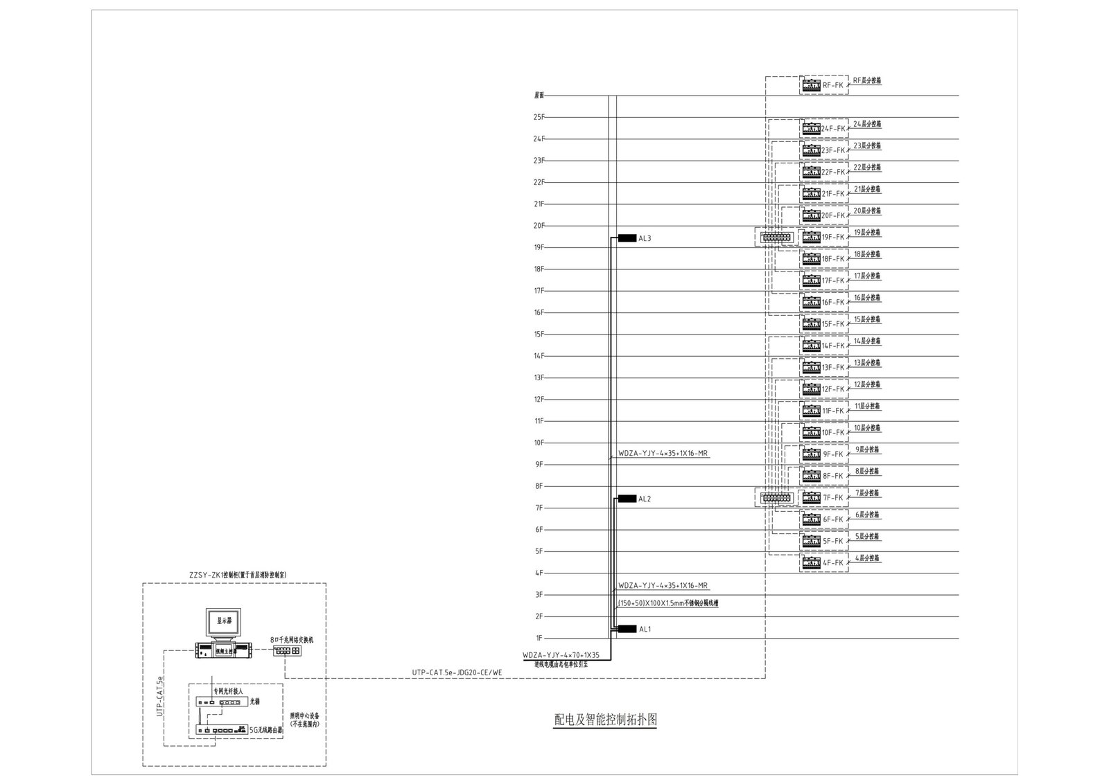
Use CAD software to compile intelligent lighting control system schematics, showing module wiring, signal transmission and scene logic relationships in detail. Contains DMX protocol interface instructions, realizes seamless connection between main control and sub-control equipment systems, and provides standardized technical basis for programming and debugging.
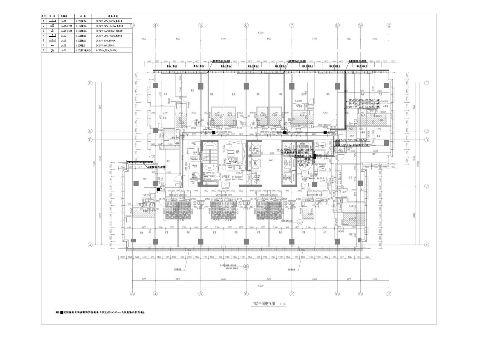
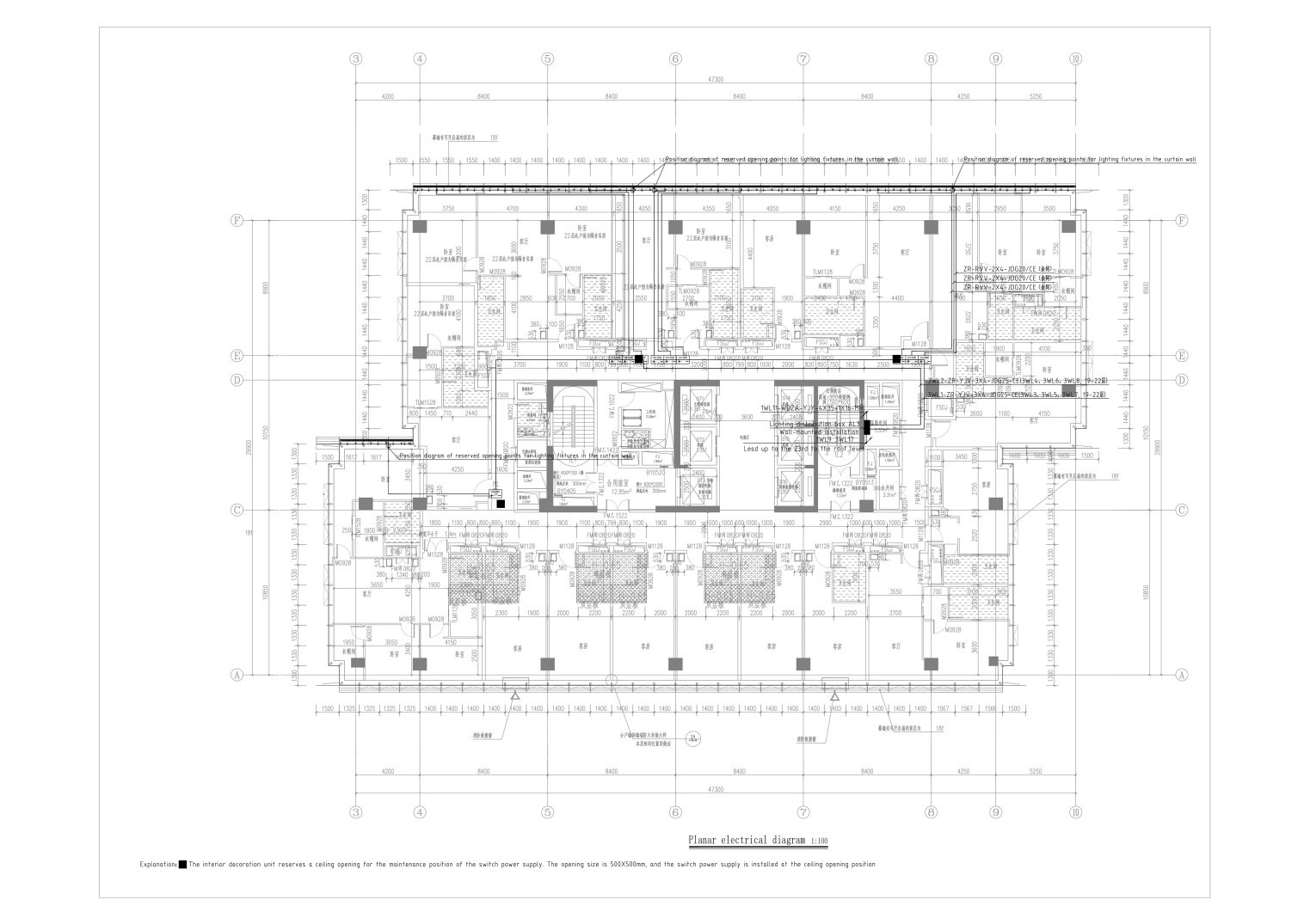
Use CAD to integrate pipelines and output refined plan diagrams including lamp positioning, loop numbering, and line pipe direction. Use different color layers and color blocks to distinguish strong and weak electricity, optimize pipeline layout to avoid crossing, reserve sufficient maintenance space, and improve construction convenience and aesthetics.
The plane control diagram fully presents the DMX control architecture, annotates the controller device location, signal path, signal amplifier linkage logic, and equipment allocation parameters, provides a standard basis for debugging and operation, and ensures stable operation of the system.
The facade electrical drawings customized for the building facade features show the lamp layout location, hidden wire trough direction, and height difference problems that cannot be displayed on the plane, and combine the plane and facade electrical diagrams to make the project complete.

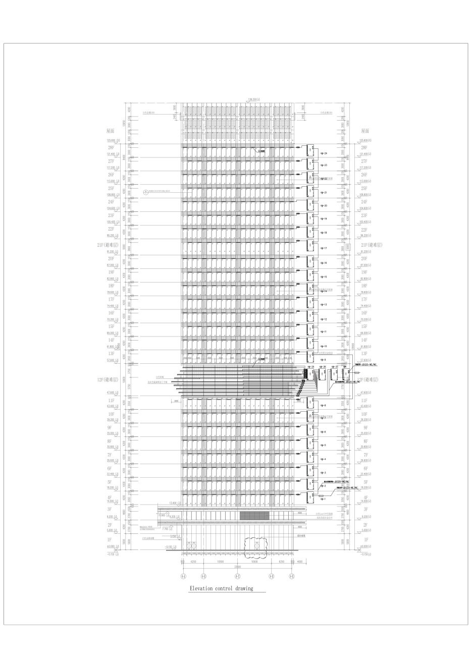
Design the elevation control drawing for the characteristic lighting design of the building elevation, including the location of the lighting, the layout of the main controller, the sub-controller, the signal amplifier, the direction of the control line and the hierarchical relationship, and combine the plane elevation control drawing to make the project display complete.
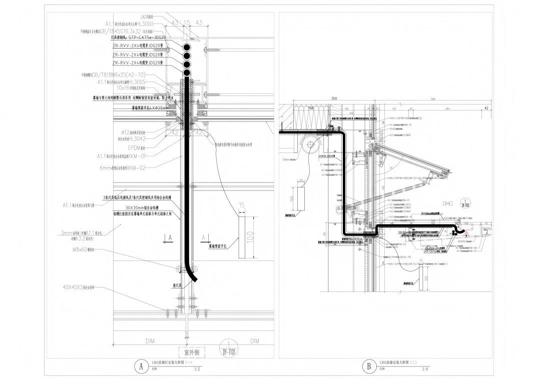
Use the node detail drawing with appropriate scale to clearly mark the installation location, fixing method and wiring specifications. It includes key process requirements such as waterproof sealing treatment and lightning protection grounding, and provides visual guidance for construction personnel with schematic diagrams and load calculation data to ensure installation accuracy and engineering quality, and effectively reduce the on-site rework rate.
Global project implementation experience